 of the neutral axis from the inside bend and the sheet thickness (T) when you bend the sheet metal.)
In our previous post, we talked about Bend Deduction and Bend Allowance. Adding more to this series of the terminology used in Sheet Metal Design, today we are going to write on the Sheet Metal K Factor.
It is worth noting that when a sheet metal piece is bent, one of the 2 portions of the sheet’s section experiences tension, and the other one goes through compression. Now the question is which portion of the section undergoes tension and which one faces compression.
Tension takes place in the portion residing along the outer/outside radius and the compression takes place in the portion residing along the inner/inside radius.
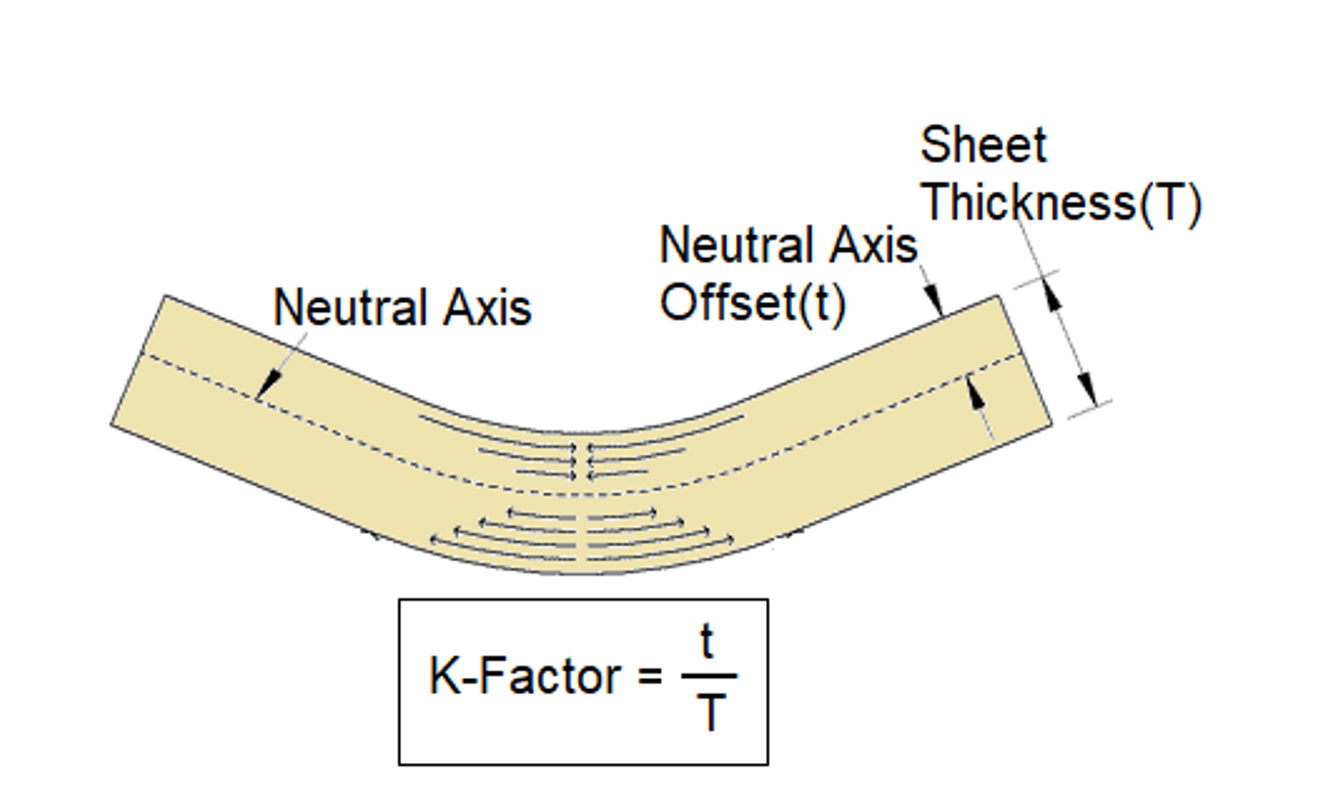
The most interesting thing is that there exists a line where there is neither tension nor compression in the section of the sheet. And, that line is referred to as Neutral Axis. This is the Neutral Axis from where the transition from tension to compression occurs.
When the sheet metal piece is in unbent/flat form, the neutral axis resides exactly in the section’s middle. And, when the sheet is bent, this axis is forced to move towards the inside bend.
Due to this relocation or displacement of the neutral axis, the distance of the axis from the inside bend changes, without affecting the length of the axis.
Types of Bends
There are four types of bends that metal has, namely: Minimum radius, Perfect, Radius, Sharp bend. The minimum radius bend reduces the radius of the metal to the least possible without causing a crease. Perfect, radius and sharp bends can be found out by using this value.
Perfect ones have values ranging from the minimum radius to 125 percent of the thickness of the metal. A radius is formed when the thickness of the metal is exceeded by 125 percent. Sharps are on the other side of the spectrum.
What is the K Factor in Sheet Metal?
K-Factor is the ratio of the distance (t) of the neutral axis from the inside bend and the sheet thickness (T) when you bend the sheet metal piece. This has been illustrated in the image given below for better understanding:
When it comes to the application of the term “K factor”, it is worth noting that it is a critical term and is used a lot in sheet metal designing.
The terms “Bend Deduction” and “Bend Allowance” are calculated with the use of the “K Factor”. And, both these 2 terms are further useful in the calculation of the flat pattern of a bent sheet.
In other words, the K-Factor is critical when it comes to the calculation and creation of the accurate design of a bent sheet’s flat pattern.
As you know the neutral axis is not positioned at the same point in all cases, the K-Factor which is also dependent on the position of the neutral axis cannot be the same for all cases. So it varies from case to case.
And, the factors affecting the value of the K-Factor are as follows:
- Material Thickness
- Inside Bend Radius
- Material’s Physical Properties
- Sheet Metal Forming Method
The value of the K-Factor can range from 0 to 0.5. However, practically, it is observed to be anywhere between 0.3 & 0.5 in general cases.
K Factor Calculator
Although it is possible to determine the K-Factor in a specific case with the use of a K Factor Chart. But you can also have a few sample pieces and run a trial if you intend to calculate by yourself. Take 3 to 5 samples and follow the below-given steps as a K Factor Calculator:
- Prepare 5 sample blanks of the same size (same width and length)
- Bend the sample pieces by using the tooling that you are going to use in the actual forming of the final pieces.
- Now, accurately measure the flange lengths of all of the samples of the sheet metal pieces. Take an average dimension out of them.
- Also, take accurate measurements of the inside bend radii of all of the bend components. [Note: You should use some devices like an optical comparator to measure the inside bend radius precisely.]
- As you have got the measurement of the flange lengths and the inside bend radii of the bend samples, now you can calculate the leg length easily. To calculate the leg lengths, you just have to deduct or subtract the inside bend radius and the material thickness from the flange lengths, if the bend angle is 90-degree.
- Now it’s time to calculate the Bend Allowance. To calculate it, you just have to subtract your leg lengths from the length of the flat pattern.
- At last, when you have got the value for the Bend Allowance, you can use a formula to calculate the K-Factor. The formula, we have shared below.
K Factor Calculator Formula
The K Factor Formula that is used to determine the value of the K-Factor for the available tooling, material, etc is given below:
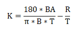
Here in this formula,
BA = Bend Allowance
B = Bend Angle in degree
T = Material Thickness
R = Inside Bend Radius
As mentioned even earlier, you can also make use of the Sheet Metal K Factor Chart for directly finding the K-Factor value if you don’t find it comfortable for you to calculate it by yourself.
K-Factor Chart
Generally, a normal range of 0 to .5 is seen in the case of standard material and thicknesses. Having said that, larger and smaller K-Factors may also be found.
For your further assistance, We have provided you with a K-Factor Chart below which you can refer, to look at common K-Factor starting points:
The chart will be posted soon…
So what do you prefer: using the K-Factor Chart or calculating the sheet metal K factor yourself with no charts? Leave a comment below to share your own opinion. If you have any queries/doubts about the topic discussed above, ask in the comments below. We will try our best to assist you.
Below we have shared some more hand-picked articles for you to read next: